Using this command, we can import files in ESRI shapefile (*.SHP), Open Geospatial Consortium Geographic Markup Language (*.GML) and GeoJSON (*.GEOJSON) formats. The program will ask for the file to be converted and will automatically draw the entities in CAD.
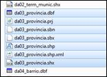
In addition to the file selected with an SHP extension, there must be other files with the same name and different extensions containing information on attributes (.dbf) and spatial indexes (.shx), which is necessary and associated with the file to be imported.
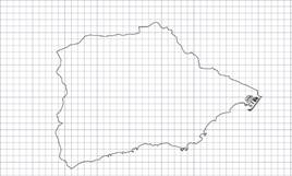
The image below shows the set of files associated with an SHP file to be imported.
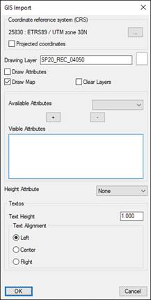
Once the file has been selected, the following window will appear in which we can manage and represent the attributes associated with the file to be imported.
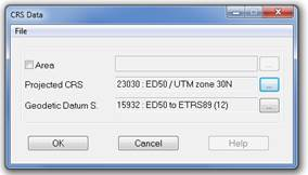
Coordinate reference system (CRS: The import also considers the possibility that the Shape or GML file is in geodesic coordinates.
If this were the situation, we would disable the box of "Projected Coordinates" and select the CRS in which the cartography that we want to import is located. The process will convert to projected coordinates automatically.
In the event that the file to be imported is in projected coordinates, we would only have to activate the corresponding box.
Drawing Layer: Layer on which the elements resultig from the import of the selected file will be drawn.
Color: By clicking on this button we can choose the color of the resulting layer and, therefore in which the entities are to be drawn.
Draw Map: This option will be enabled by default and it allows us to indicate that the lines or polylines resulting from the file import are drawn.
Clean Layer: On enabling this option we eliminate all those elements to be found in the layer we have designated to draw the elements.
Draw Attributes: Furthermore, if this option is enabled, the attributes associated with the ArcView field and which we have selected previously will be drawn.
Available Attributes: These are all the attributes to be found in the ArcView fiel selected.
Visible Attributes: Set of attributes selected and which we wish to draw when importing the ArcView file.
Texts: In this section, in the event there is any attribute to be drawn, we configure their representation from the text height to their alignment.
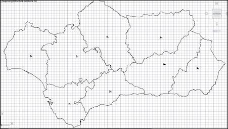
The result of importing an ArcView file with its corresponding attributes is then shown.
The Web Feature Service (WFS) is defined by the Open Geospatial Consortium (OGC) in order to provide the information related to the entity stored in a vector coverage that complies with the characteristics provided in the query.
This is a standard service featuring a communications interface to enable interaction with the maps served by the WFS standard, such as downloading information on vectors, for example.
The gml language derived from xml is used to perform these operations, which is the standard through which WFS commands are transmitted. In addition to the gml format, depending on the service, other formats such as shape or kml are available.
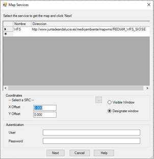
On executing the command, a window appears with a list of the different services configured in the program. This list includes a Name to identify the service, and a Web address to which the request for the map can be made. Items can be added to the list by typing on the line marked with *. Moreover, we need to specify the design of the drawing, and if we wish to obtain an image that occupies the entire visible drawing area or designate a smaller window.
To select the design of the drawing, we need to click on the browse button and the following dialogue box will appear:
When the service requires basic authentication, we enter the Username and Password to access the service.
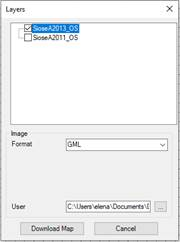
On clicking on the Next button, the program connects to the service selected from the list and another window appears in which to select the layer, in addition to the format. These options depend on the service selected.
We then name the downloaded file and choose the location by clicking on the corresponding button.
Clicking on the Download Map button will execute the file request, which will be saved in the location selected, and depending on the file format selected, the corresponding import dialogue boxes will appear automatically. The procedure for gml and shape formats will be the same as that explained in the previous section. With regard to kml format, see the Google Earth Import Kml section in the Maps/Realism module.
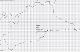
The vector information will then be placed in the drawing: