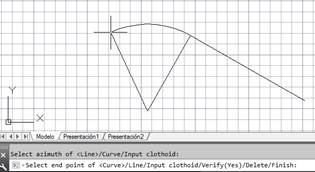
This command allows an alignment to be drawn interactively on the CAD screen. Firstly, the program asks for the initial point of the line to be designated with which the alignment starts. On the command line options appear to change the first element for a circular curve or a clothoid. Once the initial point has been entered, an initial azimuth is requested by means of a second point. In the event that the alignment starts with a line, the distance between both points will be assumed as the length of the segment. For circular curves or clothoids, once the azimuth has been entered the program requests the final point of the segment, calculating the radii and parameters automatically.
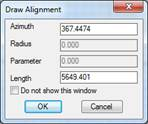
Once the first section of the alignment has been defined, a window appears in which the data entered can be checked. This window will be shown every time an alignment section is entered, unless they Do not show this window box is enabled.
For the following elements the program starts with the final azimuth of the previous element and only the final point of the section has to be entered. By default, after a line the program proposes a circular element and after a circular section a line one. A clothoid can be entered with the option Input clothoid of the command line which interactively calculates the parameter and the final radius of the clothoid as the cursor is moved. After a curve, an Output clothoid can also be entered in which, maintaining the initial radius, the parameter is calculated interactively.
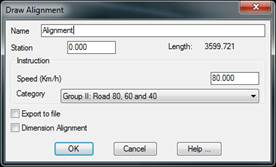
The Verify option monitors whether when entering an element, the data checking window appears and the Delete option eliminates the final section of the alignment, affording the possibility of re-entering it. Finish this completes the section input loop and shows a final window in which the initial Station can be specified, the instruction parameters etc. as well as in the command ¡Error! No se encuentra el origen de la referencia.Polyline to Alignment