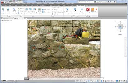
In order to be able to use this command it is necessary to insert and image and have defined at least four Reference lines or Links.
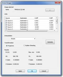
This command will ask for the selection of the image which is going to be deformed and will show the following dialogue where the file name of the selected image is shown which may be changed by designating on the screen, the list of all the Reference lines and Links related to the selected image which may be activated or deactivated to form part of the calculation, the interpolation method used to generate the final image may be selected and it may be, Next neighbours, Bilinear, Bicubic or Lagrange, the method of transformation may be selected and it may be, Projective or Rubber-Sheeting in both cases at least four pairs of points will be required. As a result, the MSE, mean square error will be shown as well as Max.Res., maximum residue, X0 and Y0, coordinates of the upper left-hand point of the image, Scale in X and Y in m/pixel and X and Y Rotation.
The Apply button allows the viewing of the result of the Deformation before endorsing the operation. By pressing OK the adjustment is endorsed and the image is inserted at the coordinates resulting from the transformation, the destination directory will be requested for the generated image and its corresponding georeference file and the Reference lines, Links and Marks which have been involved in the transformation will be deleted. When pressing the Cancel button, the operation is cancelled and all the elements are restored.
The main difference between the Projective transformation and Rubber-Sheeting method is the numbers of points that may be adjusted, in the case of projective, four points may be adjusted as maximum, in the case of Rubber-Sheeting, all points involved of the calculation may be adjusted.