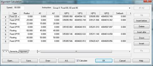
This command allows an alignment to be edited based on the elements that define it. Upon executing the command, an alignment can be selected on the screen or the command line options can be used to load a file or create a new alignment. A window then appears with the list of elements, ordered according to the direction of travel of the alignment.
Firstly, the alignment project speed appears and road instruction file. The A1 A2 button assigns to the alignment of the list which has the cursor the clothoid parameters in accordance with the instruction.
Under the list there are two tabs labelled Elements and Alignments. The first allows the editing of the elements and the second shows the alignment resulting from the calculation.
On the right of the window there is an operations' column which operates on the alignment selected on the list. The Up and Down buttons allow an alignment to be moved within the list. The Delete button eliminates it and the Invert button exchanges the initial and final points of the alignment as well as the radius sign, resulting in the inversion of the direction of travel of the alignment at this alignment. For an element which is not fixed and which has been calculated, the Fix button converts it into a fixed alignment, taking its initial and final points from the calculation. Finally, the Insert before and Insert after buttons allow the graphic designation of a layout element and its addition to the list, being inserted at the position before or after that of the cursor.
On the list itself in the first column (Type) the element type can be changed, selecting it from a drop-down menu. When changing the type, the other cells on the row can be enabled or disabled in line with the option chosen.
The Radius, A1 and A2 columns allow the radius and the input (A1) and output (A2) clothoid parameters of the corresponding element to be edited. By pressing the lower button, A/L, you can switch between the parameter or length when editing the clothoids.
The columns X(P1), Y(P1), X(P2) and Y(P2) show the coordinates defined by the fixed elements. In the rest of the elements they are disabled, except at the revolving (or back-revolving) elements in which the crossing point is shown at X(P1), Y(P1). These coordinates can be coordinated by keying in a value or pressing the "..." button to designate the point graphically.
The Setback column shows the displacement that fixed elements may have.
The Length and Inclength are involved in the coupled elements. The former is the length of the coupled element and the latter is the modification to the length of the element to which it is coupled.
In the event that on the lower part the Calculate option is enabled, each edition of the list brings about a recalculation of the alignments affected. In the event that the program is unable to calculate any alignment, in the first column the cell with the ordinal of the alignment will appear in red. Upon placing the cursor on this line, under the list the error that has occurred appears on the status line.
The Open button allows a segment or alignment file to be loaded. The Save button allows the list of elements to be saved on a file. In the event that it is not possible to calculate the alignment, the file to be save will be of the alignment type (with the extension ALI). When the alignment can be calculated, the file to be saved will be of the alignment type (with the extension EJE), but including the information pertaining to the alignments. Hence, in future sessions the same set of alignments can continue to be edited.