This command constitutes an extremely useful tool to enter a horizontal alignment from a list.
MDT will initially request the horizontal alignment to be edited or created (either graphically or by selecting a file) and then display the following dialog box whose features and functions are described below.
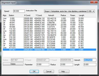
The horizontal alignment’s configuration appears in the upper part, that is to say, the Speed of the road to be defined and the type of road it will be associated with (Instruction File). These values will be essential for the subsequent superelevation calculation.
A list then appears showing the alignment’s unique points should they have existed previously. In the lower part, a there is a control for each of the alignment’s components, including: Station, XCoordinate, YCoordinate, Azimuth, Parameter, Radius and Length.
As each of these fields is filled in, the rest will be calculated automatically although all values must be entered for the first point.
For instance, if entry clothoid with its radius and parameter is entered, the length of the next point will be calculated automatically together with the new vertex’s coordinates.
Delete: If this button is activated, the unique point of the horizontal alignment selected on the list will be deleted and the horizontal alignment will be recalculated automatically from the remaining vertices.
Once the dialog box has been validated, the changes will be saved in the file selected. If a horizontal alignment has been designated graphically, the changes will be reflected in the drawing.