10.17.3. Vertical Alignment’s Panel
Under the CAD view we’ll see a panel with the current alignment’s information.
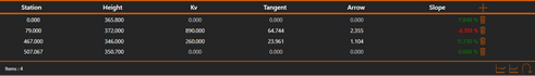
Node list:
For each alignment’s node, the following information is shown in the list. From left to right:
· Station: The node’s Station. It can be edited by double clicking it, it can only be confirmed if the new station doesn’t provoke an overlap.
· Height: The node’s Height. It can be edited by double clicking it, it can only be confirmed if the new height doesn’t provoke an overlap.
· Kv: Node’s vertical curve. It can be edited by double clicking it, it can only be confirmed if the new Kv doesn’t provoke an overlap.
· Tangent: Node’s tangent’s length. It can be edited by double clicking it, it can only be confirmed if the new tangent doesn’t provoke an overlap.
· Arrow: Node’s arrow’s length. It can be edited by double clicking it, it can only be confirmed if the new arrow doesn’t provoke an overlap.
· Slope: The node’s slope value. It’s the slope between that node and the next one. The slope direction is defined by the value’s sign. Positive slopes are displayed with a green text, negative ones with a red text.
·  Remove: Removes the vertical alignment’s node.
Vertical alignment’s tools:
At the panel’s bottom right, we can find specific vertical alignment edition tools: