4.4. Set Current Surface |
This command sets the surface file that is now considered the current surface. This will be the surface taken by default for generating contours, create profiles, etc.
If the drawing is in the same folder in which there are already surface and mesh files, the following window will appear with the files detected in the same folder.
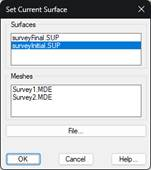
If the surface that we are going to set as current is in the same folder, we select it in the window and press the OK button. In the event that the surface or mesh file is in another folder, press the File... and select the same one according to the folder in which it is located.
When you select the surface and press the OK button, the following dialog will appear where the type of representation of the surface is configured.
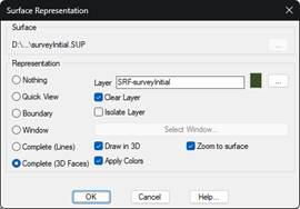
Layer: By default the layer name will be the one set in the application settings, where the suffix is the surface name. This suffix allow us to draw several surfaces in the same drawing and on different layers. Anyway, we have the possibility to change the name of the layer by pressing the button (...).
Representation; We have different possibilities in terms of the representation of the surface in the CAD, it will be established as current regardless of the one selected.
· Nothing: It does not represent anything in the drawing.
· Quick View: With this option, we get a representation of the surface at the current zoom level, the moment we change the zoom or move in the drawing window, the surface will be erased.
· Boundary: It only represents the outline of the surface with a closed polyline.
· Window: We select a window and the surface will be drawn only within the selected window.
· Complete (Lines): The entire surface will be drawn with line type entities.
· Complete (3D Faces): The entire surface will be drawn with 3d faces type entities. If you enable the Apply Colors option, the cells will take on the texture according to the surface file.
§ Draw in 3D: If this option is enabled, the surface, in the case of selecting the Lines option, will be made in 3D.
Compared to previous versions of MDT, there is the possibility of establishing a binary mesh file as the current surface. The advantage is that for very dense models, a binary mesh file takes up significantly less memory than the equivalent surface file, and its handling is more efficient. This advantage has the trade-off that the binary mesh has a regular cell interval, unlike a surface made of triangles, where any coordinate can be used as the vertex of a triangle.
|
|