9.23.2. Rotation Angles
This numerical data element will label the rotation angle of each of the power line supports or poles.
These will only be drawn in the event the “Draw Power Lines” option has been activated and the file corresponding to the power lines has been selected.
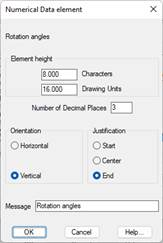
Element height: Represents the distance to the immediately previous numerical data element. This value may be expressed in two different formats:
· Expressed in number of characters.
· Expressed in drawing units.
On validating either of these formats, the other value will be recalculated automatically.
Number of Decimal Places: Any numbers in the text in the column selected will be represented with the decimal places indicated.
Orientation: Establishes the orientation of the texts. There are two possibilities, Horizontal or Vertical.
Justification: Establishes the position of the text in relation to the point of insertion. There are three possibilities: Start, Center and End.
Colors: Possibility to customize the color of the horizontal line and the texts associated with the element that is represented.
Message: Text that will appear as the title of the element in the drawing.
Chain Type
This numerical data element labels the chain type of each of the power line poles. There are two types of chain: Moorage and Suspension.
These will only be drawn in the event the Draw Power Lines option has been activated and the file corresponding to the power lines has been selected.
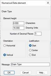
Element height: Represents the distance to the immediately previous numerical data element. This value may be expressed in two different formats:
· Expressed in number of characters.
· Expressed in drawing units.
On validating either of these formats, the other value will be recalculated automatically.
Number of Decimal Places: Any numbers in the text in the column selected will be represented with the decimal places indicated.
Orientation: Establishes the orientation of the texts. There are two possibilities, Horizontal or Vertical.
Justification: Establishes the position of the text in relation to the point of insertion. There are three possibilities: Start, Center and End.
Colors: Possibility to customize the color of the horizontal line and the texts associated with the element that is represented.
Message: Text that will appear as the title of the element in the drawing.
Distance between poles
This numerical data element labels the distance between each of the power line supports or poles.
These will only be drawn in the event the Draw Power Lines option has been activated and the file corresponding to the power lines has been selected.
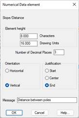
Element height: Represents the distance to the immediately previous numerical data element. This value may be expressed in two different formats:
· Expressed in number of characters.
· Expressed in drawing units.
On validating either of these formats, the other value will be recalculated automatically.
Number of Decimal Places: Any numbers in the text in the selected column will be represented with the decimals indicated.
Orientation: Establishes the orientation of the texts. There are two possibilities, Horizontal or Vertical.
Justification: Establishes the position of the text in relation to the point of insertion. There are three possibilities: Start, Center and End.
Station format: Possibility of labelling the station with the extended format (contains the symbol +).
Orientation: Establishes the orientation of the texts. There are two possibilities, Horizontal or Vertical.
Justification: Establishes the position of the text in relation to the point of insertion. There are three possibilities: Start, Center and End.
Colors: Possibility to customize the color of the horizontal line and the texts associated with the element that is represented.
Message: Text that will appear as the title of the element in the drawing.
|
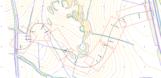
Draw Cartography Sheets
|
This option will allow us to draw a format of leaves on the floor of the selected alignment. This command is complementary to Draw Simple Profileor Draw Compound Profile so that, once the sheets are drawn, the contents of each of the sheets are reflected in the drawing of the long section.
Initially the following window appears:
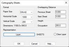
Paper Size: Sheet format to be inserted.
Scale: Horizontal and vertical scale.
Occupation: value that indicates the height of the sheet. The dimensions of the selected paper format are reported, in this section we will introduce a value so that the height of the sheet can be drawn next to the profile.
Overlaping Distance: We indicate the overlap values of each sheet with the front and back sheet.
Representation: Layer in which the representation of the leaves will be made.
|
|