16.4.2. Print
When selecting this option, the data on the list is dumped into the selected printer.
Draw
The points designated graphically or by file, when pressing this button will be drawn automatically.
|
Label Points on Alignment
|
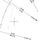
With this command we will be able to label marks in the drawing with the characteristics of the point with respect to the selected alignment.
Initially, we see the next window in which we select the information we want to label.
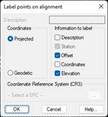
Information to label
Description: By selecting this option, the Description field in which we will enter the text that we want to label will be enabled.
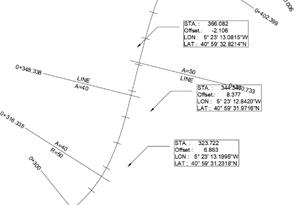
Station: The station result of the analysis of the designated point with respect to the alignment will be labeled.
Offset: The offset resulting from the analysis of the designated point with respect to the alignment will be labeled.
Coordinates: The X and Y coordinates of the designated point are labeled.
Elevation: The elevation of the designated point is displayed if the Z of the point is non-zero.
Coordinates
By showing the coordinates, we have the possibility of labeling the projected coordinates, that is, the designated X and Y or the geodesic coordinates.
In the case of selecting the Geodesic option, it is necessary to select the Coordinate Reference System.
|
Analysis of Points with Respect to Road
|
This option is very much geared towards controlling a linear work that is in progress. The command enables one to conduct analyses and control a surveying conducted on MDT done from cross-section templates with horizontal alignments on the ground plan and elevation drawing obtained from the theoretical status of the terrain in a linear work. These files can either have come from being fully completed with other applications or from files imported from other applications.
There are three methods of calculation: using a Surface, using the Typical section or the Grade line. In the latter two cases, it will request the segment of the road.
In both cases we must select the Points to analyze. Likewise, for both methods, the maximum permissible tolerance values Positive and Negative are defined. If the difference between the real and theoretical elevation exceeds these limits, the point is considered unacceptable, and is marked with an asterisk (*).
There are three methods to select points, either from a point file, by selecting MDT points or by designating coordinates on the screen. In the case of selecting the dot file, the expected format is N, X, Y, Z, separated by spaces or tabs.