9.22.22. Power line poles
This numerical data element is aimed at representing power lines, although it can be used more generally. It represents the partial distance between two SUPPORT codes on the long section to be represented. The dialog box shown below is then displayed A description of its characteristics follows.
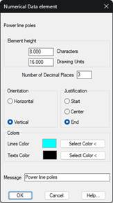
Element Height: Represents the distance to the immediately preceding numerical data element, expressed in number of characters. This value may be expressed in two different ways:
· In number of characters
· In drawing units
When either of them is validated, the other value is automatically recalculated.
Number of Decimals: Number of decimals with which the lengths of the partial distances between the supports are to be represented.
Orientation: Sets the texts’ orientation. There are two possibilities, either Horizontal or Vertical.
Justification: Sets the position of the text in relation to the insertion point. There are three possibilities: Start, Center and End.
Terrain: The long section to which the element refers should be selected. By default, 1 is equivalent to the profile contained in the segment. If another number is selected, it will be related to the profile entered in the Terrain option.
Colors: Possibility to customize the color of the horizontal line and the texts associated with the element that is represented.
Message: Text that will appear as the element’s title on the numerical data drawing.