4.24. Generate Proposed Terrain |
This command allows one to obtain the final status of the project’s surface after earthworks. First one must select a segment file, or a horizontal alignment and a cross-section file, usually generated using the Cross-Sections > Generate Modified Terrain command. The following dialog box is then displayed:
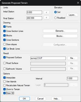
The Initial Station and Final Station fields allow one to select the area of action along the horizontal alignment’s length. Initially, it takes the minimum and maximum possible values, subtracted from the horizontal alignment and the cross-section profiles.
The cross-section template to be considered is specified in the Elevation box. Should the roadbed have multiple layers, a specific layer may be selected using the Layers button.
The program’s different possibilities are individually controlled in the Drawing section.
· Points: The program creates a surveying point at each of the cross-section’s vertices. Each point is assigned the vertex as a code.
· Cross-Section Lines: Polylines are drawn on the ground plan representing the different components of the cross-section template. Once can decide whether each of them will be drawn by clicking on the Elements button.
· Blocks: Represents the blocks on the ground plan in accordance with the block assignment performed for the segment.
· Cross-Sections: A polyline is drawn with each of the natural terrain cuts.
· Slope Drawings: Additional representations of the slopes.
· Cut Break Lines: Deletes polylines drawn within the occupation environment on the layers used for break lines to create the current surface.
Results
Proposed Surface: Surface in which the area resulting from the merger of the one established as current with that generated by the road will be stored.
Road Surface: Surface generated by the road.
Earthwork Volume: Possibility of creating an MT file, this file contains the information of volumes in this case of the road. It is very useful for exporting to IFC format. See the BIM section > Export to IFC.
The modification of the current surface can be enabled in the Result section. By default, the program proposes a name for the surface file, so that it does not coincide with any existing files.
A drawing of the polylines on the ground plan having greater definition is obtained using the Interpolate option. The program will not only consider the modified cross-section’s vertices but also create new vertices between the cuts according to the distance specified in Interval.
By enabling the Use Islands option, one can define areas with closed polylines where the command will not make any modifications. This could be useful for road intersections, branches, etc.
Recalculate Natural Terrain makes the program internally recalculate the cross-section profile from the current surface. Thus, if various modifications have been made to the surface, the area of cutting and fill slopes could be affected by the surface’s status without having to generate and include a cross-section profile in the segment that reflects such changes.
Draw 3D: If we activate this option, once the vial and the modified surface have been generated, a 3D view will be built in realistic mode.
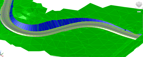
Example of proposed terrain
|
|