11.25. Draw on Top View |
Using this command allows one to draw the cross-sections obtained. The dialog box that is displayed when the command is executed is shown below.
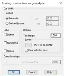
Method: Select the drawing type for the cuts in ground plan view.
· Automatic: In this case the width of the cross-section drawing in ground plan will be the one that corresponds in the selected cross-section file. So that depending on the width of each cut, there may be cuts with different right and left lengths.
· Defined by user: For this case, on the contrary, we specify in the Left and Right fields the width that we want the cross-sections to have in ground plan, which is the same for all cuts.
Label Station, Numbering and Slopes: When drawing the cross-sections in plan view, if we have activated any of these two options will be labeled next to the transverse.
Label Station and Numbering: When the cross-section is drawn on the ground plan, these options will be labelled next to the cross-sections if either of them is activated
Group: This allows one to group all the lines representing the cross-sections to be drawn in a single block. It makes it easier to adjust or delete them subsequently.
Text Height: One specifies the height of the texts used to label in this box if the relevant check boxes have been marked.
Layers: One selects the layer on which the cross-sections will be drawn on the ground plan. The program proposes the TRANS layer by default.
Clear selected layer: If this box is checked, all the entities found in the layer selected for the cuts drawing will be deleted.
Control overlaps (Distance on slope): If the labeling of the slopes is selected, a minimum distance can be established between the texts to be labeled so that they do not overlap.
Once the dialog box has been validated, MDT will draw them with the options selected.
|
|