5.14. Draw Mesh |
This command allows one to represent a mesh file obtained by using the Meshes > Create Mesh from Surface or Meshes > Create Mesh from Contour Lines tools. First, the program requests a mesh file (ASCII or binary). The following dialog box is then displayed:
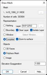
One can choose between two kinds of objects to draw a mesh: The Polyface Mesh option has the advantage of being quicker and the disadvantage that CAD sets a maximum limit on the number of vertices and faces. This is why the default option is 3D Faces.
In addition, there is the option of drawing the mesh as an image and this method will allow us to create an Image from the mesh file. To be precise, an image will be created in TIFFformat.
By clicking the Select button, one can specify a layer other than the one proposed by the program. Clear Layer removes the objects from the layer before drawing the mesh and Isolate Layer hides the drawing’s other drawing layers.
The Elevation Exaggeration parameter is used to multiply the mesh’s elevation values in order to increase or decrease cell elevation differences and improve the viewing of relief. Lastly, once the representation is finished, the Zoom check box ensures the screen is framed on the mesh area. In should be considered that the drawing is in three dimensions. It is therefore necessary to execute one of the CAD commands to change the viewpoint like, for example, VPOINT.
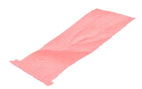
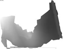
Drawing with 3D Faces Drawing as an image
|
|