14.4. Create Nodes from Drawing |
This command enables us to create nodes automatically from existing entities in the drawing. It features different possibilities depending on the type of entity you wish to interpret. Initially, the following window will appear, from which we will describe the characteristics.
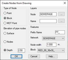
Type of Node: The type of entity that we are going to convert into a node; there are three possibilities:
· Point: Refers to the CAD point entity.
· Block: The CAD insertion block.
· MDT point: The point object created by MDT
Layers: We specify the layers in which the entities to be converted are located.
· Node: The layer in which the entity to be convert into a node is located.
· Name: The layer in which the text that refers to the name of the node is located. If no layer is specified, a name will be assigned by default.
Elevation of pipe nodes: Shows how to calculate the grade line elevation assigned to the node by default.
· Surface: The grade used will be the elevation of the surface at the insertion point.
· Nodes: The grade line elevation used will be the elevation of the entity to be converted.
· Depth: The grade used will be the result of subtracting the specified depth from the ground elevation.
The ground elevation will always be the elevation of the surface at the insertion point of the entity to be converted if there is a surface.
Features
· Prefix Name: The option of adding a prefix to the name of the node.
· Network: The type of network to which the converted node will be assigned.
· Node width: The default width of the node resulting from the conversion
· Block: Representative block for each of the nodes to be converted.
After clicking on the OK button, the entities will be automatically converted in accordance with the options selected.
|
|