13.3.1. Create Link
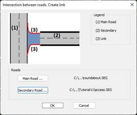
It is the initial command, where we will indicate the segment corresponding to the Main Road and the Secondary Road. The following window will appear in which, graphically you can see the function of each road.
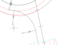
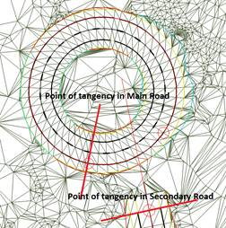
When validating the dialogue, it will ask us for the points of tangency in the main and secondary segment, these points of tangency will correspond to the beginning and end of the link.
Once the points of tangency have been designated, the following window will appear in which we define the alignment of the corresponding side.
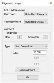
Link. Platform vectors: We indicate the coupling vector of the link alignment, both in the main and secondary roads.
Tangents: Possibility to change the position of the tangency points selected in the previous point.
Type: Type of alignment. It is possible to select three options:
· Line – Curve – Line: We define an alignment with a circular one between two lines. Request the radius of the circular.
· Clothoid – Curve – Clothoid: In this type of alignment we specify the parameter of the input clothoid, the radius of the circular and the parameter of the output clothoid.
· Designate: In this case, we have previously defined an axis or polyline that represents the alignment of our horn, it will ask us to designate it.
Draw Alignment: For types 1 and 2, when pressing the button, the alignment will be drawn with the indicated parameters, this option gives us the possibility of performing different tests until reaching the appropriate alignment.
When validating the dialog, the alignment will be drawn automatically and a segment with the alignment will be created. It is on this segment that the following commands will be worked. By default, the segment name will be constructed from the name of the parent and secondary segment and the action side.