9.10. Convert from Segment |
These tools are used to generate a long section from a previously defined segment or road. Thus, we can select the displacement of the desired horizontal alignment and from which source of information we wish to obtain the height of the different profile vertices.
On executing this command, the following dialog box will appear, which is described below:
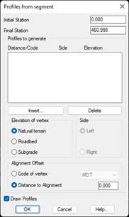
Initial Station: Initial station of the new profile to be generated.
Final Station: Final station of the new profile to be generated.
Elevation of Vertex: We indicate the source of information from which we wish to generate the elevations of the new profile to be generated. A choice can be made between the elevations of existing ground, roadbed or subgrade in the case that roadbed exists in the defined segment.
Distance to Alignment: The offset to horizontal alignment for the profile generation. This can be indicated with a code, which should coincide with one of the vertex codes of the cross-section profiles existing in the segment, or it can be indicated as a displacement value.
Side: This indicates whether we want the longitudinal to generate to the left or right of the horizontal alignment.
With the buttons Insert and Delete, we manage the different profiles to be generated according to the selection made in the previous parameters.
When OK, it will ask us for the prefix of the name of the file, to this name the characteristics of each profile will be concatenated, generating in this way a longitudinal file for each existing element in the list.
Finally, if we activate the Draw Profiles option, we will have the possibility to draw all the profiles generated simultaneously.
|
|