3.16. Check Break Lines |
Break lines are very useful to define relief effects. However, it is essential to have a tool available to check such lines. This command has therefore been implemented, which enables errors to be detected by drawing a series of marks on specific layers. The different error detection possibilities that can be activated in the dialog box designed for this purpose are described below:
Detect Loose Vertices: Determines polyline vertices in which there are no surveying points. The marks are represented on the ERROR_VERTICES layer.
Detect Points on Line: Finds the surveying points closest to polylines considered as break lines, and which should possibly be its vertex. They are drawn on the ERROR_POINTS layer.
Detect Crosses: Examines the crossings between break lines, which could possibly be due to an interpretation fault. The errors are drawn on the ERROR_CROSSES layer.
Check 3D Polylines: Checks whether there is a height difference between surveying points and polyline vertices.
Check Surfaces: Determines whether the break lines are included on the current surface. If there is an error, it is represented on the ERROR_SUP layer.
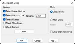
The Radius parameter defines the circumference used to mark possible errors on the drawing. Clean Error from Layers deletes all objects from the layers used to mark the errors.
The Layers button allows one to select the layers to be checked for possible errors.
Once the faults in the break lines that could considerably distort the digital terrain model have been detected, they can be checked either manually by creating a layer on which the errors are displayed or automatically by generating points where the error has been detected, activating error marks or creating points, respectively.